Logic Gates
Logic gates can be made of resistors, transistors or diodes. These components are wired together in specific configurations to ensure they transform the inputs in expected ways.
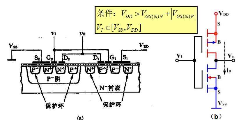
CMOS (complementary metal-oxide-semiconductor)
- 静态功耗低
- 电源电压范围宽
- 输入阻抗高
- 逻辑摆幅大
- 噪声容限大,抗干扰能力强
- 扇出能力强
- 温度稳定性好,且有较强的抗辐射能力
- 集成度高,成本低
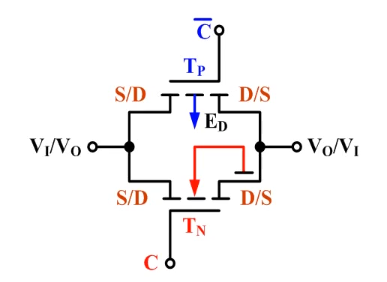
CMOS TG (translation gate)
General logic gates
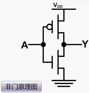
- Tri-state buffer / Inverter
~A/ NOT
| Input(A) | Output Y |
|---|---|
| 0 | 1 |
| 1 | 0 |
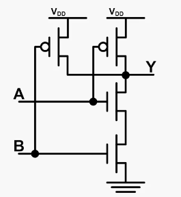
- AND
A & B=nor + not
| Input(A) | Input(B) | Output |
|---|---|---|
| 0 | 0 | 0 |
| 0 | 1 | 0 |
| 1 | 0 | 0 |
| 1 | 1 | 1 |
- OR
A | B
| Input(A) | Input(B) | Output |
|---|---|---|
| 0 | 0 | 0 |
| 0 | 1 | 1 |
| 1 | 0 | 1 |
| 1 | 1 | 1 |
- XOR
A ^ B
| Input(A) | Input(B) | Output |
|---|---|---|
| 0 | 0 | 0 |
| 0 | 1 | 1 |
| 1 | 0 | 1 |
| 1 | 1 | 0 |
- NAND
!(A & B)
| Input(A) | Input(B) | Output |
|---|---|---|
| 0 | 0 | 1 |
| 0 | 1 | 1 |
| 1 | 0 | 1 |
| 1 | 1 | 0 |
- NOR
!(A | B)
| Input(A) | Input(B) | Output |
|---|---|---|
| 0 | 0 | 1 |
| 0 | 1 | 0 |
| 1 | 0 | 0 |
| 1 | 1 | 0 |
- XNOR
!(A ^ B)
| Input(A) | Input(B) | Output |
|---|---|---|
| 0 | 0 | 1 |
| 0 | 1 | 0 |
| 1 | 0 | 0 |
| 1 | 1 | 1 |
SR-Latch (Set & Reset Latch)
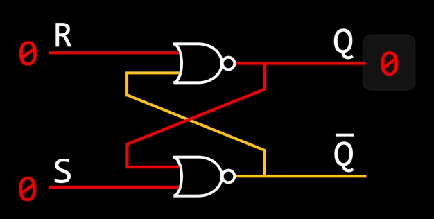
| S | R | Q | Q Invert |
|---|---|---|---|
| 0 | 0 | latch | latch |
| 0 | 1 | 0 | 1 |
| 1 | 0 | 1 | 0 |
| 1 | 1 | 0 | 0 |
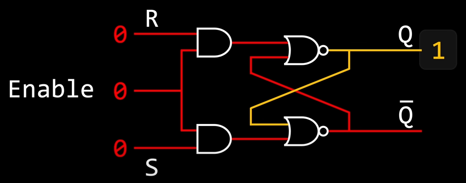
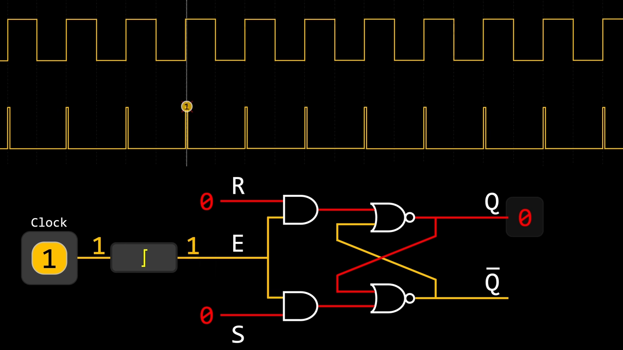
Gated SR-Latch
Half add
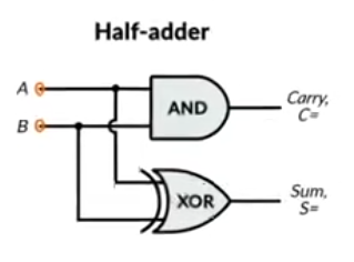
| Input(A) | Input(B) | Output(Sum) | Output(Carry) |
|---|---|---|---|
| 0 | 0 | 0 | 0 |
| 0 | 1 | 1 | 0 |
| 1 | 0 | 1 | 0 |
| 1 | 1 | 0 | 1 |
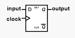
D flip-flop
Full add
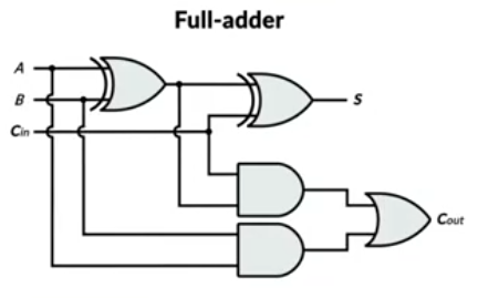
| Input(A) | Input(B) | Input(Cin) | Output(Sum) | Output(Carry) |
|---|---|---|---|---|
| 0 | 0 | 0 | 0 | 0 |
| 0 | 0 | 1 | 1 | 0 |
| 0 | 1 | 0 | 1 | 0 |
| 0 | 1 | 1 | 0 | 1 |
| 1 | 0 | 0 | 1 | 0 |
| 1 | 0 | 1 | 0 | 1 |
| 1 | 1 | 0 | 0 | 1 |
| 1 | 1 | 1 | 1 | 1 |
4-bit add

- Rising edge detector using clock singal
- Alias: Ripple-Carry Adder, RCA
- Optimized: Carry-Lookahead Adder, CLA
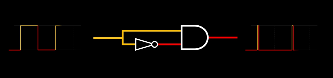
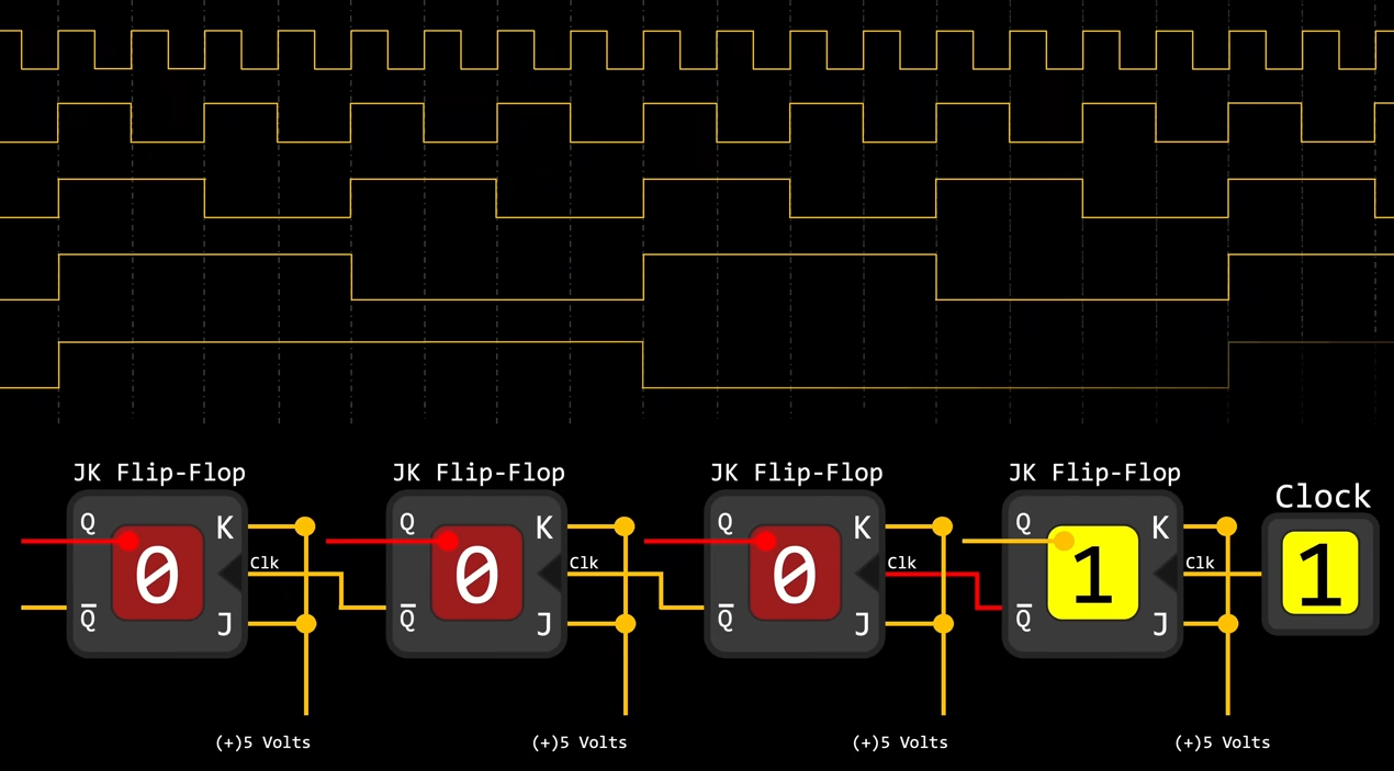
- Rising edge triggers enabled state
- On Rising edge, J performs set function, K performs reset function, if both J and K are High, the result depends on stored value Q, i.e, the stored value toggles
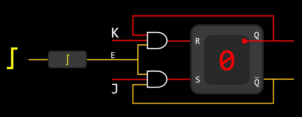
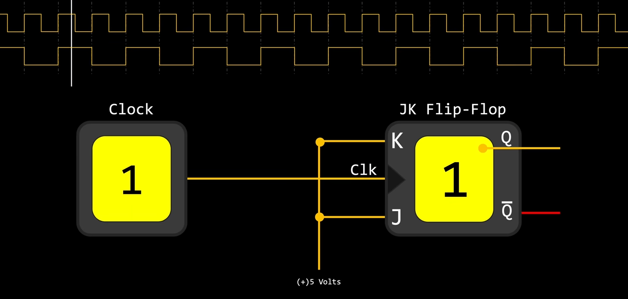
- JK Flip-Flop
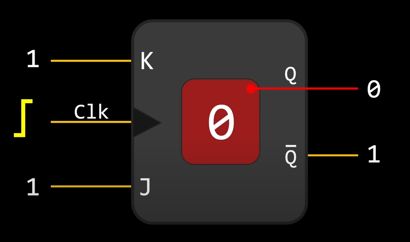
SR-LatchSet & Reset Latch
| J | K | Clk | Q | Q Invert |
|---|---|---|---|---|
| 0 | 0 | enable | latch | latch |
| 0 | 1 | enable | 0 | 1 |
| 1 | 0 | enable | 1 | 0 |
| 1 | 1 | enable | toggle | toggle |
- Half Singal With
- Binary Decoder
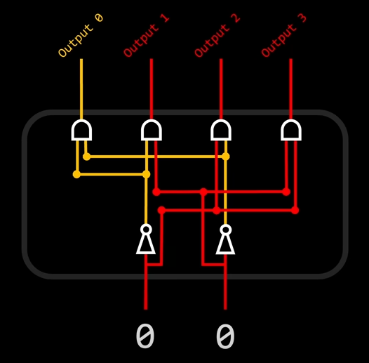
| S | R | out0 | out1 | out2 | out3 |
|---|---|---|---|---|---|
| 0 | 0 | 1 | 0 | 0 | 0 |
| 0 | 1 | 0 | 1 | 0 | 0 |
| 1 | 0 | 0 | 0 | 1 | 0 |
| 1 | 1 | 0 | 0 | 0 | 1 |
- Binary counter, by chain Flip-Flop, every clock rising edge cause 0000 rising by 1, 1111 -> 0000, act as a binary counter
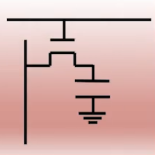
Open Drain vs Push-Pull
- Open drain is a term used for MOS(Metal Oxide Semiconductor) chips in the same way that open collector is used for TTL(Transistor to Transistor Logic) chips;
what is a register
- https://electronics.stackexchange.com/questions/37946/what-is-the-main-difference-between-registers-bit-fields-and-flags
- https://www.coursera.org/learn/jisuanji-zucheng/lecture/isrpm/303-ji-cun-qi-de-ji-ben-yuan-li
DRAM
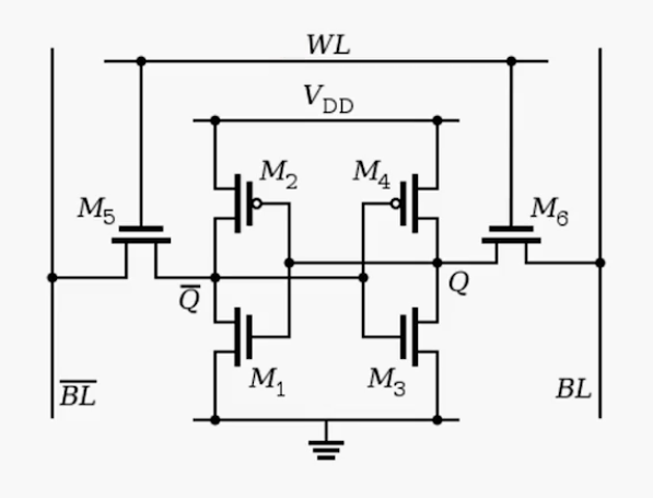
SRAM
Page Source