Serial Peripheral Interface (SPI)
Serial Peripheral Interface (SPI) is an interface bus commonly used to send data between microcontrollers and small peripherals such as shift registers, sensors, and SD cards. It uses separate clock and data lines, along with a select line to choose the device you wish to talk to.
4 Pins
| Master/Slave (OLD) | Controller/Peripheral (NEW) |
|---|---|
| Master In Slave Out (MISO) | Controller In, Peripheral Out (CIPO) |
| Master Out Slave In (MOSI) | Controller Out Peripheral In (COPI) |
| Slave Select pin (SS) | Chip Select Pin (CS) |
| SPI Clock (SPICLK) | Clock (CLK) |
What’s Wrong with Serial Ports?
A common serial port, the kind with TX and RX lines, is called “asynchronous” (not synchronous) because there is no control over when data is sent or any guarantee that both sides are running at precisely the same rate. Since computers normally rely on everything being synchronized to a single “clock” (the main crystal attached to a computer that drives everything), this can be a problem when two systems with slightly different clocks try to communicate with each other.
To work around this problem, asynchronous serial connections add extra start and stop bits to each byte help the receiver sync up to data as it arrives. Both sides must also agree on the transmission speed (such as 9600 bits per second) in advance. Slight differences in the transmission rate aren’t a problem because the receiver re-syncs at the start of each byte.
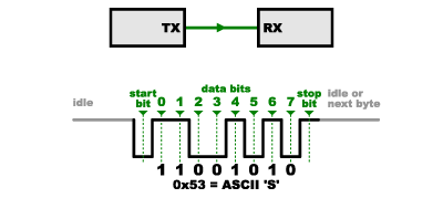
Asynchronous serial works just fine, but has a lot of overhead in both the extra start and stop bits sent with every byte, and the complex hardware required to send and receive data. And as you’ve probably noticed in your own projects, if both sides aren’t set to the same speed, the received data will be garbage. This is because the receiver is sampling the bits at very specific times (the arrows in the above diagram). If the receiver is looking at the wrong times, it will see the wrong bits.
A Synchronous Solution
SPI works in a slightly different manner. It’s a “synchronous” data bus, which means that it uses separate lines for data and a “clock” that keeps both sides in perfect sync. The clock is an oscillating signal that tells the receiver exactly when to sample the bits on the data line. This could be the rising (low to high) or falling (high to low) edge of the clock signal; the datasheet will specify which one to use. When the receiver detects that edge, it will immediately look at the data line to read the next bit (see the arrows in the below diagram). Because the clock is sent along with the data, specifying the speed isn’t important, although devices will have a top speed at which they can operate (We’ll discuss choosing the proper clock edge and speed in a bit).
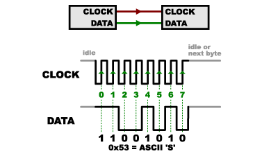
One reason that SPI is so popular is that the receiving hardware can be a simple shift register. This is a much simpler (and cheaper!) piece of hardware than the full-up UART (Universal Asynchronous Receiver / Transmitter) that asynchronous serial requires.
Receiving Data
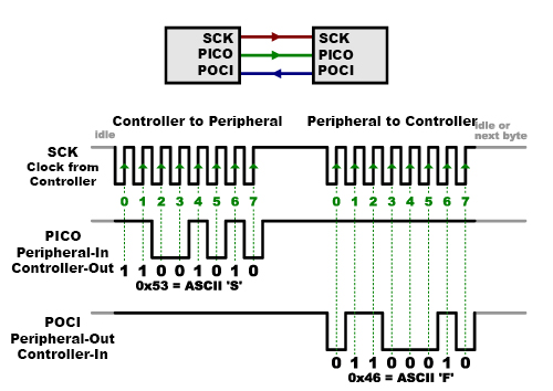
In SPI, only one side generates the clock signal (usually called CLK or SCK for Serial ClocK). The side that generates the clock is called the “controller”, and the other side is called the “peripheral”. There is always only one controller (which is almost always your microcontroller), but there can be multiple peripherals (more on this in a bit).
When data is sent from the controller to a peripheral, it’s sent on a data line called PICO, for “Peripheral In / Controller Out”. If the peripheral needs to send a response back to the controller, the controller will continue to generate a prearranged number of clock cycles, and the peripheral will put the data onto a third data line called POCI, for “Peripheral Out / Controller In”.