SERIAL COMMUNCIATION
Introduction
Embedded electronics is all about interlinking circuits (processors or other integrated circuits) to create a symbiotic system. In order for those individual circuits to swap their information, they must share a common communication protocol. Hundreds of communication protocols have been defined to achieve this data exchange, and, in general, each can be separated into one of two categories: parallel or serial.
Parallel vs. Serial
Parallel interfaces transfer multiple bits at the same time. They usually require buses of data - transmitting across eight, sixteen, or more wires. Data is transferred in huge, crashing waves of 1’s and 0’s.
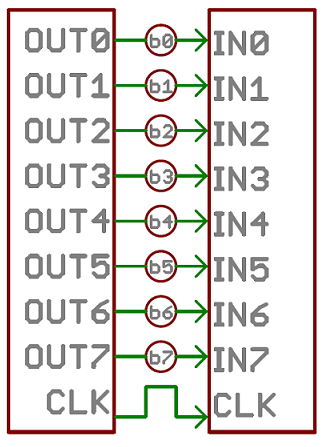 An 8-bit data bus, controlled by a clock, transmitting a byte every clock pulse. 9 wires are used.
Serial interfaces stream their data, one single bit at a time. These interfaces can operate on as little as one wire, usually never more than four.
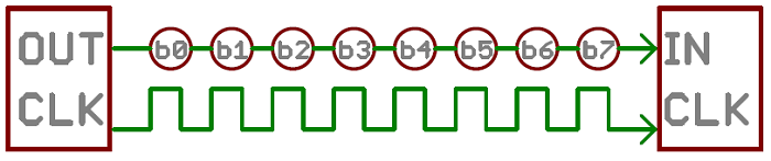 Example of a serial interface, transmitting one bit every clock pulse. Just 2 wires required!
Think of the two interfaces as a stream of cars: a parallel interface would be the 8+ lane mega-highway, while a serial interface is more like a two-lane rural country road. Over a set amount of time, the mega-highway potentially gets more people to their destinations, but that rural two-laner serves its purpose and costs a fraction of the funds to build.
Parallel communication certainly has its benefits. It’s fast, straightforward, and relatively easy to implement. But it requires many more input/output (I/O) lines. If you’ve ever had to move a project from a basic Arduino Uno to a Mega, you know that the I/O lines on a microprocessor can be precious and few. So, we often opt for serial communication, sacrificing potential speed for pin real estate.
Asynchronous Serial
Over the years, dozens of serial protocols have been crafted to meet particular needs of embedded systems. USB (universal serial bus), and Ethernet, are a couple of the more well-known computing serial interfaces. Other very common serial interfaces include SPI, I2C, and the serial standard we’re here to talk about today. Each of these serial interfaces can be sorted into one of two groups: synchronous or asynchronous.
A synchronous serial interface always pairs its data line(s) with a clock signal, so all devices on a synchronous serial bus share a common clock. This makes for a more straightforward, often faster serial transfer, but it also requires at least one extra wire between communicating devices. Examples of synchronous interfaces include SPI, and I2C.
Asynchronous means that data is transferred without support from an external clock signal. This transmission method is perfect for minimizing the required wires and I/O pins, but it does mean we need to put some extra effort into reliably transferring and receiving data. The serial protocol we’ll be discussing in this tutorial is the most common form of asynchronous transfers. It is so common, in fact, that when most folks say “serial” they’re talking about this protocol (something you’ll probably notice throughout this tutorial).
The clock-less serial protocol we’ll be discussing in this tutorial is widely used in embedded electronics. If you’re looking to add a GPS module, Bluetooth, XBee’s, serial LCDs, or many other external devices to your project, you’ll probably need to whip out some serial-fu.
Analog vs. Digital
We live in an analog world. There are an infinite amount of colors to paint an object (even if the difference is indiscernible to our eye), there are an infinite number of tones we can hear, and there are an infinite number of smells we can smell. The common theme among all of these analog signals is their infinite possibilities.
Digital signals and objects deal in the realm of the discrete or finite, meaning there is a limited set of values they can be. That could mean just two total possible values, 255, 4,294,967,296, or anything as long as it’s not ∞ (infinity).
RS-232 vs. TTL
Most microcontrollers these days have built in UARTs (universally asynchronous receiver/transmitter) that can be used to receive and transmit data serially. UARTs transmit one bit at a time at a specified data rate (i.e. 9600bps, 115200bps, etc.). This method of serial communication is sometimes referred to as TTL serial (transistor-transistor logic). Serial communication at a TTL level will always remain between the limits of 0V and Vcc, which is often 5V or 3.3V. A logic high (‘1’) is represented by Vcc, while a logic low (‘0’) is 0V.
The serial port on your computer (if it’s lucky enough to have one, they’re quickly becoming a relic) complies with the RS-232 (Recommended Standard 232) telecommunications standard. RS-232 signals are similar to your microcontroller’s serial signals in that they transmit one bit at a time, at a specific baud rate, with or without parity and/or stop bits. The two differ solely at a hardware level. By the RS-232 standard a logic high (‘1’) is represented by a negative voltage – anywhere from -3 to -25V – while a logic low (‘0’) transmits a positive voltage that can be anywhere from +3 to +25V. On most PCs these signals swing from -13 to +13V.
The more extreme voltages of an RS-232 signal help to make it less susceptible to noise, interference, and degradation. This means that an RS-232 signal can generally travel longer physical distances than their TTL counterparts, while still providing a reliable data transmission.
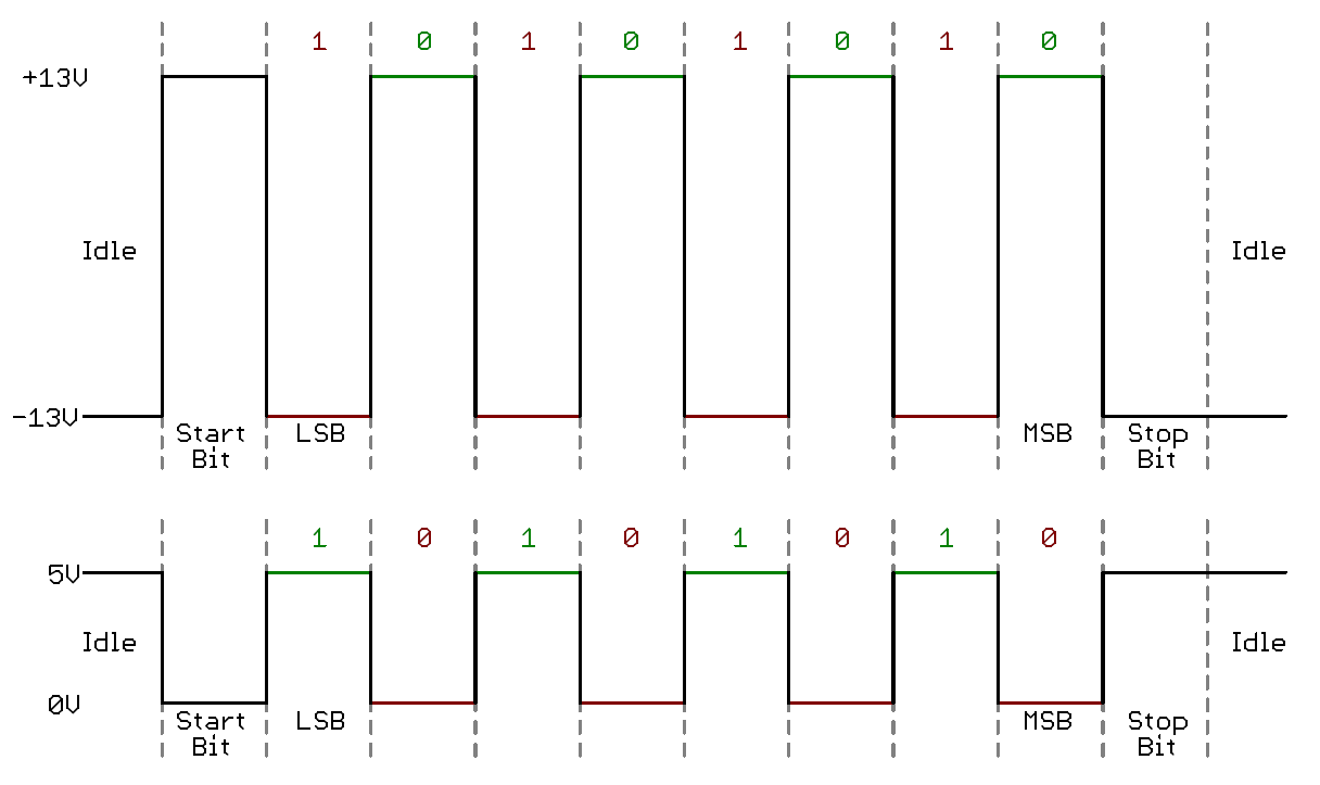 This timing diagram shows both a TTL (bottom) and RS-232 signal sending 0b01010101
TTY vs CU (Mac, Linux)
In Unix and Linux environments, each serial communication port has two parts to it, a tty* and a cu*
The difference between the two is that a TTY device is used to call into a device/system, and the CU device (call-up) is used to call out of a device/system. Thus, this allows for two-way communication at the same time (full-duplex)