Logic Gates
Logic gates can be made of resistors, transistors or diodes. These components are wired together in specific configurations to ensure they transform the inputs in expected ways.
##
- Tri-state buffer / Inverter
~A
| Input(A) | Output |
|---|---|
| 0 | 1 |
| 1 | 0 |
- AND
A & B
| Input(A) | Input(B) | Output |
|---|---|---|
| 0 | 0 | 0 |
| 0 | 1 | 0 |
| 1 | 0 | 0 |
| 1 | 1 | 1 |
- OR
A | B
| Input(A) | Input(B) | Output |
|---|---|---|
| 0 | 0 | 0 |
| 0 | 1 | 1 |
| 1 | 0 | 1 |
| 1 | 1 | 1 |
- XOR
A ^ B
| Input(A) | Input(B) | Output |
|---|---|---|
| 0 | 0 | 0 |
| 0 | 1 | 1 |
| 1 | 0 | 1 |
| 1 | 1 | 0 |
- NAND
!(A & B)
| Input(A) | Input(B) | Output |
|---|---|---|
| 0 | 0 | 1 |
| 0 | 1 | 1 |
| 1 | 0 | 1 |
| 1 | 1 | 0 |
- NOR
!(A | B)
| Input(A) | Input(B) | Output |
|---|---|---|
| 0 | 0 | 1 |
| 0 | 1 | 0 |
| 1 | 0 | 0 |
| 1 | 1 | 0 |
- XNOR
!(A ^ B)
| Input(A) | Input(B) | Output |
|---|---|---|
| 0 | 0 | 1 |
| 0 | 1 | 0 |
| 1 | 0 | 0 |
| 1 | 1 | 1 |
Half add
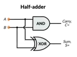
| Input(A) | Input(B) | Output(Sum) | Output(Carry) |
|---|---|---|---|
| 0 | 0 | 0 | 0 |
| 0 | 1 | 1 | 0 |
| 1 | 0 | 1 | 0 |
| 1 | 1 | 0 | 1 |
Full add
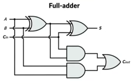
| Input(A) | Input(B) | Input(Cin) | Output(Sum) | Output(Carry) |
|---|---|---|---|---|
| 0 | 0 | 0 | 0 | 0 |
| 0 | 0 | 1 | 1 | 0 |
| 0 | 1 | 0 | 1 | 0 |
| 0 | 1 | 1 | 0 | 1 |
| 1 | 0 | 0 | 1 | 0 |
| 1 | 0 | 1 | 0 | 1 |
| 1 | 1 | 0 | 0 | 1 |
| 1 | 1 | 1 | 1 | 1 |
4-bit add

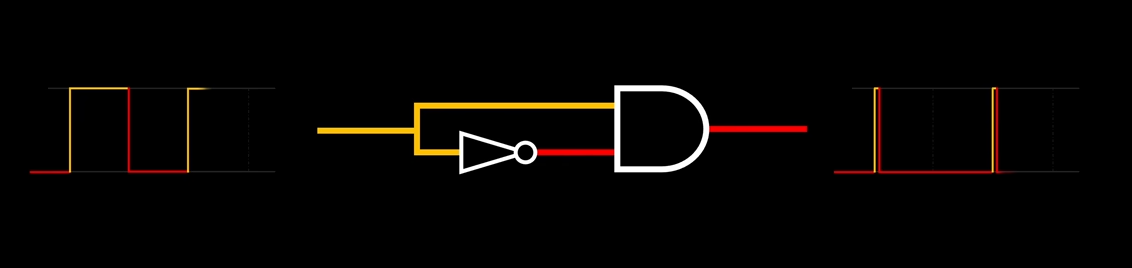
- Rising edge detector using clock singal
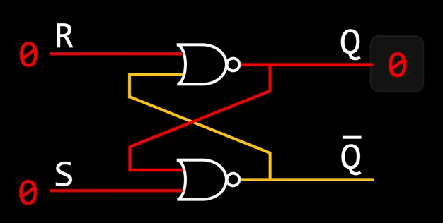
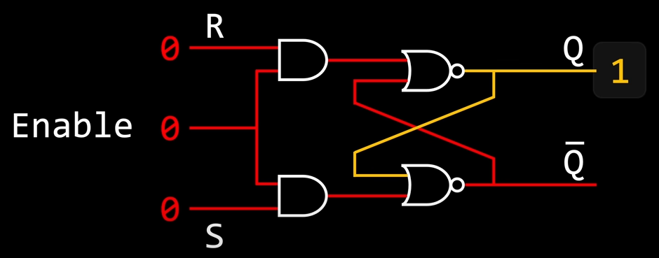
SR-LatchSet & Reset Latch
| S | R | Q | Q Invert |
|---|---|---|---|
| 0 | 0 | latch | latch |
| 0 | 1 | 0 | 1 |
| 1 | 0 | 1 | 0 |
| 1 | 1 | 0 | 0 |
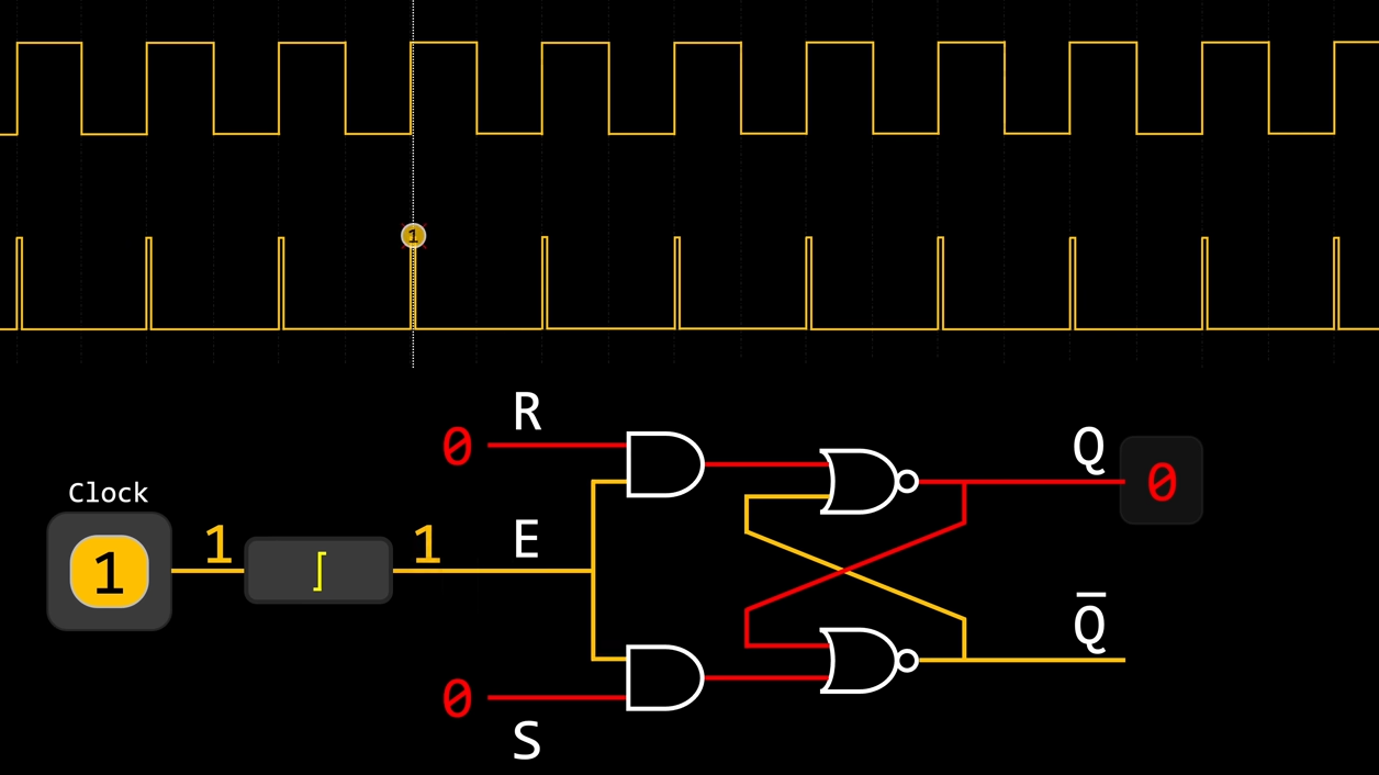
- Gated SR-Latch
- Rising edge triggers enabled state
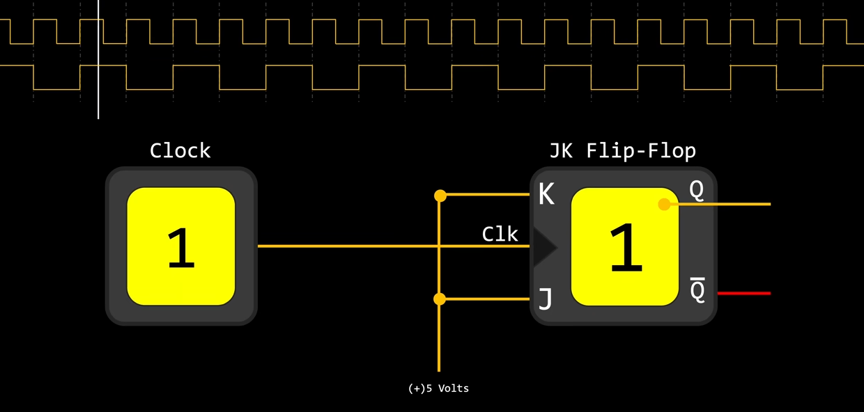
- On Rising edge, J performs set function, K performs reset function, if both J and K are High, the result depends on stored value Q, i.e, the stored value toggles
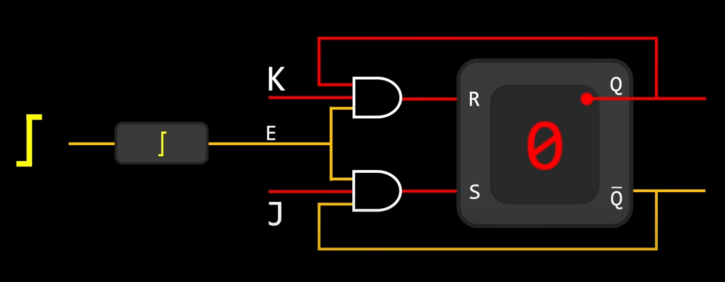
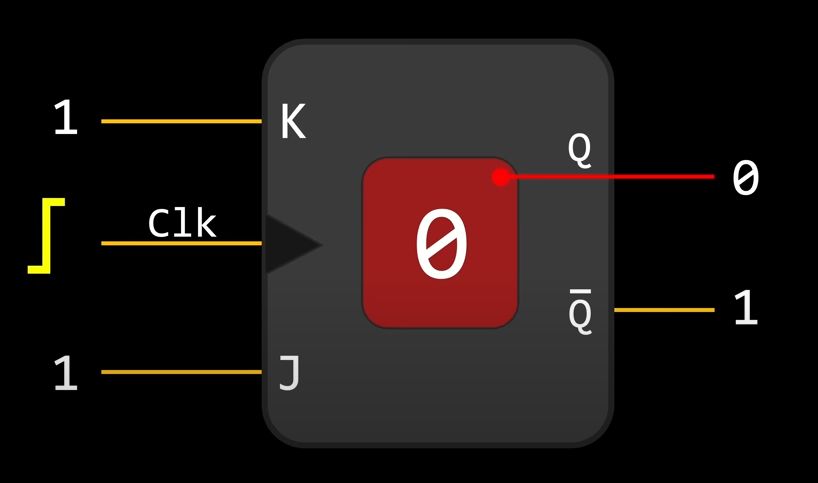
- JK Flip-Flop
SR-LatchSet & Reset Latch
| J | K | Clk | Q | Q Invert |
|---|---|---|---|---|
| 0 | 0 | enable | latch | latch |
| 0 | 1 | enable | 0 | 1 |
| 1 | 0 | enable | 1 | 0 |
| 1 | 1 | enable | toggle | toggle |
- Half Singal With
- Binary Decoder
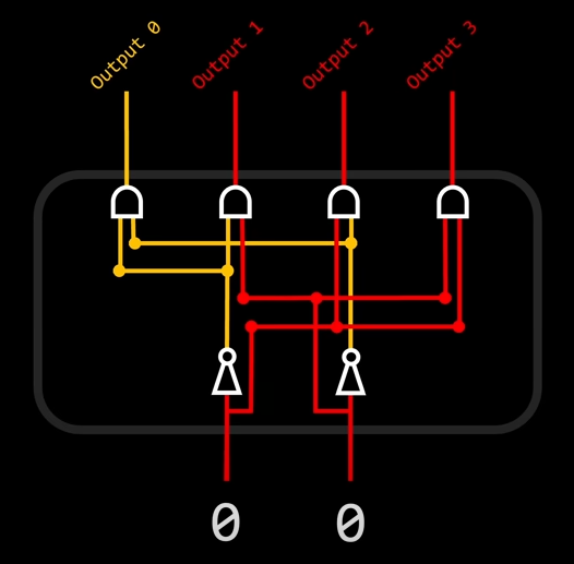
| S | R | out0 | out1 | out2 | out3 |
|---|---|---|---|---|---|
| 0 | 0 | 1 | 0 | 0 | 0 |
| 0 | 1 | 0 | 1 | 0 | 0 |
| 1 | 0 | 0 | 0 | 1 | 0 |
| 1 | 1 | 0 | 0 | 0 | 1 |
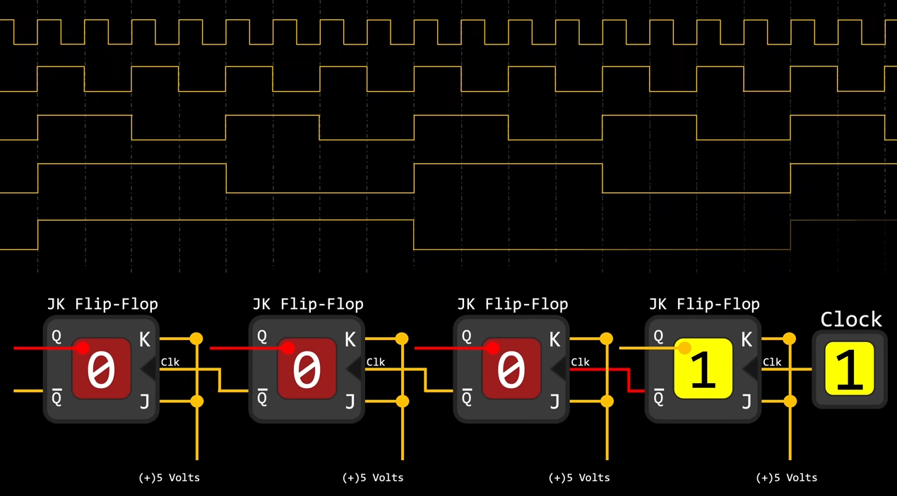
- Binary counter, by chain Flip-Flop, every clock rising edge cause 0000 rising by 1, 1111 -> 0000, act as a binary counter
Open Drain vs Push-Pull
- Open drain is a term used for MOS(Metal Oxide Semiconductor) chips in the same way that open collector is used for TTL(Transistor to Transistor Logic) chips;